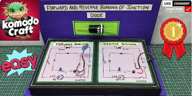
Creating a Forward and Reverse biasing of junction diode working model for school project in few easy steps
| Materials | Required |
|---|---|
| Resistor | Wire |
| Battery connector | On/off switch |
| Diode | Small light |
Table of Contents
Table of Contents
Steps to Create the Working Model
Step 1: Set Up for Forward Biasing
- Place the diode on the breadboard.
- The anode (P-side) is the longer lead, and the cathode (N-side) is the shorter lead.
- Connect the P-side to the positive terminal of the battery and the N-side to the negative terminal using wires.
- Add a resistor in series with the diode to protect it from high current.
- If you’re using an LED, connect it in series with the diode to indicate the current flow.
Step 2: Observe Forward Biasing
- Turn on the power supply.
- You should see the LED light up, indicating that current is flowing through the diode.
- Use the multimeter to measure the voltage across the diode (it should be around 0.7V for a silicon diode).
Step 3: Set Up for Reverse Biasing
- Reverse the connections of the diode:
- Connect the P-side to the negative terminal of the battery.
- Connect the N-side to the positive terminal.
- Keep the resistor and LED in the circuit as before.
Step 4: Observe Reverse Biasing
- Turn on the power supply.
- The LED will not light up because the diode is blocking the current.
- Use the multimeter to measure the voltage across the diode (it should match the battery voltage).
Related Posts – Young double slit working model
Explanation of the Model
1. Forward Biasing:
Current flows when the diode is forward-one-sided.
Make sense of how the consumption locale becomes more slender, permitting electrons and openings to get across the intersection.
Show the illuminated Drove as proof of current stream.
Why Forward Biasing is Important
Forward biasing is useful because it allows the diode to act as a switch that conducts electricity. This property is used in circuits like:
- Converting AC (alternating current) to DC (direct current).
- Protecting devices from electrical surges.
2. Reverse Biasing:
Current is obstructed when the diode is reverse-one-sided.
Make sense of how the consumption locale enlarges, halting the progression of charge transporters.
Show the dark Drove as proof that no current is streaming.
Why Reverse Biasing is Important
Reverse biasing is helpful in many ways, such as:
- Blocking unwanted current in circuits.
- Storing energy in capacitors.
- Stabilizing voltage in power supplies (using special diodes like Zener diodes).
What is a Junction Diode?
A junction diode is made up of two layers of semiconductors:
P (positive): This side has more openings (positive charge carriers).
N (negative): This side has more electrons (negative charge carriers).
Where these two layers meet is called the PN junction.
When we connect the diode to a power supply, it behaves differently depending on the connection. This is where forward biasing and reverse biasing come in.
What Happens Inside the Diode?’
To understand forward and reverse biasing better, we should investigate what happens inside the diode:
Electrons and Holes Move:
In forward bias, electrons and holes move toward one another, permitting current to stream.
In reverse bias, they move away from one another, halting the progression of current.
Energy Hindrance Changes: The outside voltage changes the size of the exhaustion locale, which behaves like an entryway for the current.
Heat and Light Production: in certain diodes (like LEDs), the movement of electrons and holes produces heat and light.
How to Present Your Model
- Visual Appeal:
Put your circuit on a flawless board or stage.
Use names to stamp the diode, resistor, battery, and LED.
Incorporate a little chart of forward and switch biasing.
2. Clarification Graph:
Make an outline making sense of the ideas of forward and switch biasing.
Add graphs of the PN intersection in the two states.
3. Live Exhibition:
During your presentation, show how the LED illuminates in forward biasing and remains off backward biasing.
Utilize the multimeter readings to back up your clarification.
Additional Tips for Progress
Figure out the Essentials: Ensure you completely comprehend how a diode functions so you can with certainty answer questions.
Practice the steps: Test your circuit on numerous occasions to guarantee everything works impeccably during the presentation.
Add Fun Elements: If conceivable, utilize a signal or a second LED to make the show really captivating.
Why This Project is Useful
Real-Life Applications:
Diodes are utilized in gadgets like chargers, radios, and even televisions. Understanding their working is fundamental for learning gadgets.
Interactive Learning: Building the model assists you with learning better by doing rather than simply perusing.
Impress Your Teachers:
A completely ready model with a reasonable clarification shows your diligent effort and comprehension of the topic.
Conclusion
Making a functioning model of forward and switch biasing of an intersection diode is a cool science project as well as an extraordinary method for understanding how diodes work in real life. With basic materials and an unmistakable clarification, you can exhibit the vital ideas of gadgets and flabbergast your teachers and schoolmates.
Thus, assemble your materials, follow these means, and prepare to sparkle in your school project. Best of luck, and have a good time learning! 😊